 1 1 |
 2 2 |
 3 3 |
 4 4 |
 5 5 |
 6 6 |
 7 7 |
 8 8 |
 9 9 |
 10 10 |
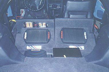
When I designed the system, I knew there was going to be a lot involved in the system as far as number of components were concerned, so I tried to mazimize utilization of space as much as possible. I also wanted to keep enough space for usage. This is my daily driver car and I travel a LOT. If I go on vacation, I want to have room to travel comfortably and have room to pack stuff. This is why the processor ended up in the back of the passenger seat. And the amps landed in the back of the rear seats - replace foam with amplifiers!
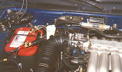
Everything starts with the power source. When the installation was originally done, the factory battery was left in. No upgraded alternator was added, factory is 120 amps. But I was going to be using a pair of 1-farad capacitors, one for each of the large amplifiers. Within six months of doing the original installation, things had to change. I discarded the factory battery and added the Optima 800. MAN what a difference! I could leave my car off (for more than 10 minutes) and the stereo running without killing it! That was probably the best change I made (well, at that time). The Optima 800 was added in, but was smaller than the bulky factory battery, so the bracket to secure it was modified to hold the more compact Optima. Rockford Fosgate gold battery terminals were used to connect everything to the battery.
Power is delivered to the system with 2 gauge cable from SoundQuest. The master system fuse is housed on a custom bracket mounted in the rear-center of the engine compartment and is 17" in wire-length from the battery terminal. It is loomed from terminal to firewall.
Once the cable runs through the firewall, it runs along the lower driver side of the car behind factory plastic panels that house and protect cables along both sides of the car. All power cables use the driver side, all signal cables use the right side. The power cable runs along the edge and up to the rear seats.
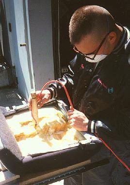
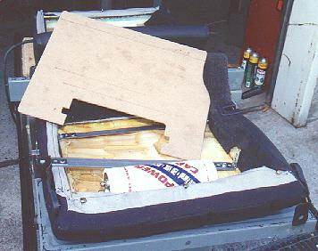
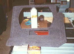
Picture 2 shows the process the rear seats went through. First, all the factory cross/support brackets were removed (but not the primary outer structure). Using custom tools - yes, Larry built custom foam-cutting tools using the straightened heater coil from a hair drier and a power source. The resultant smell was awful but they went right through the foam with pure simplicity. Saved chancing slicing through the vinyl from using a utility knife. Picture 3 shows where things were headed with mounting recessed custom brackets, the cap, and masonite to hold the amp.
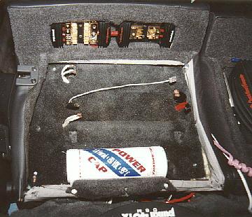
The brackets were recessed in about 2 inches with all wires tied. The distrubution blocks were in the "lip" at the top of the driver-side rear seat. The 2 gauge cable goes along the edge of the seat up to it, then dual 8 gauge goes to the amps. Two Rockford Power Blocks were used to distribute power to the amps and neon. These are shown in greater detail in picture 10.
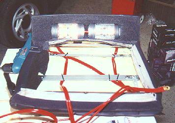
As things progressed, the seats were put back in the car and wires connected. The pieces of 1/4" masonite were covered with carpet and mounted to the recessed brackets (picture 5). This provided full support for the foam in the seats and provides plenty of rigidity to support someone sitting the the rear seats. Holes were cut in appropriate places and power, speaker, and PSD cables were run to their respective locations for mounting the amps.
The caps are housed, also recessed, below each amplifier. They are held in place with the brackets they came with which are attached to the lower structre of the rear seat and the support brackets that were recessed in for holding the amps.
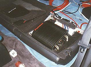
Picture 6 shows the amplifier mounted in place with the endcap removed.
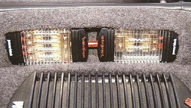
The original panels that covered the back of the rear seats were used, but were cut to custom fit the amps and a window left to display each of the caps (picture 7). The original brackets to hold the panels in place were also used.
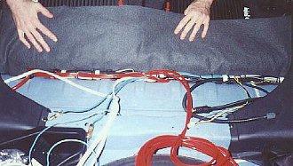
All of the wiring to everything was tied and run along the edge of the seats. The lower body of the car drops down for the bottom of the back seats, and is flat toward the back. At that "pivot point" is where the seats hinge. This is where all the cables were run. Power to the amps. Speaker wires. Cables from the changer to the processor. Power to the neon. Picture 8 shows this. Everything was covered using grey carpet.The final mounting of the amps is shown in Picture 9. They are a Rockford Fosgate Punch Power 250m2 driving the front left/right stage mounted in the driver-side rear seat. The passenger side houses the Punch Power 500m driving the subs, running 2-ohm mono. Each of these amps is directly connected to their respective 1-farad Gel America power cap. You can also see the Power Blocks in the final 2 pictures.
Covered on the next page are the changer and rear amp.

